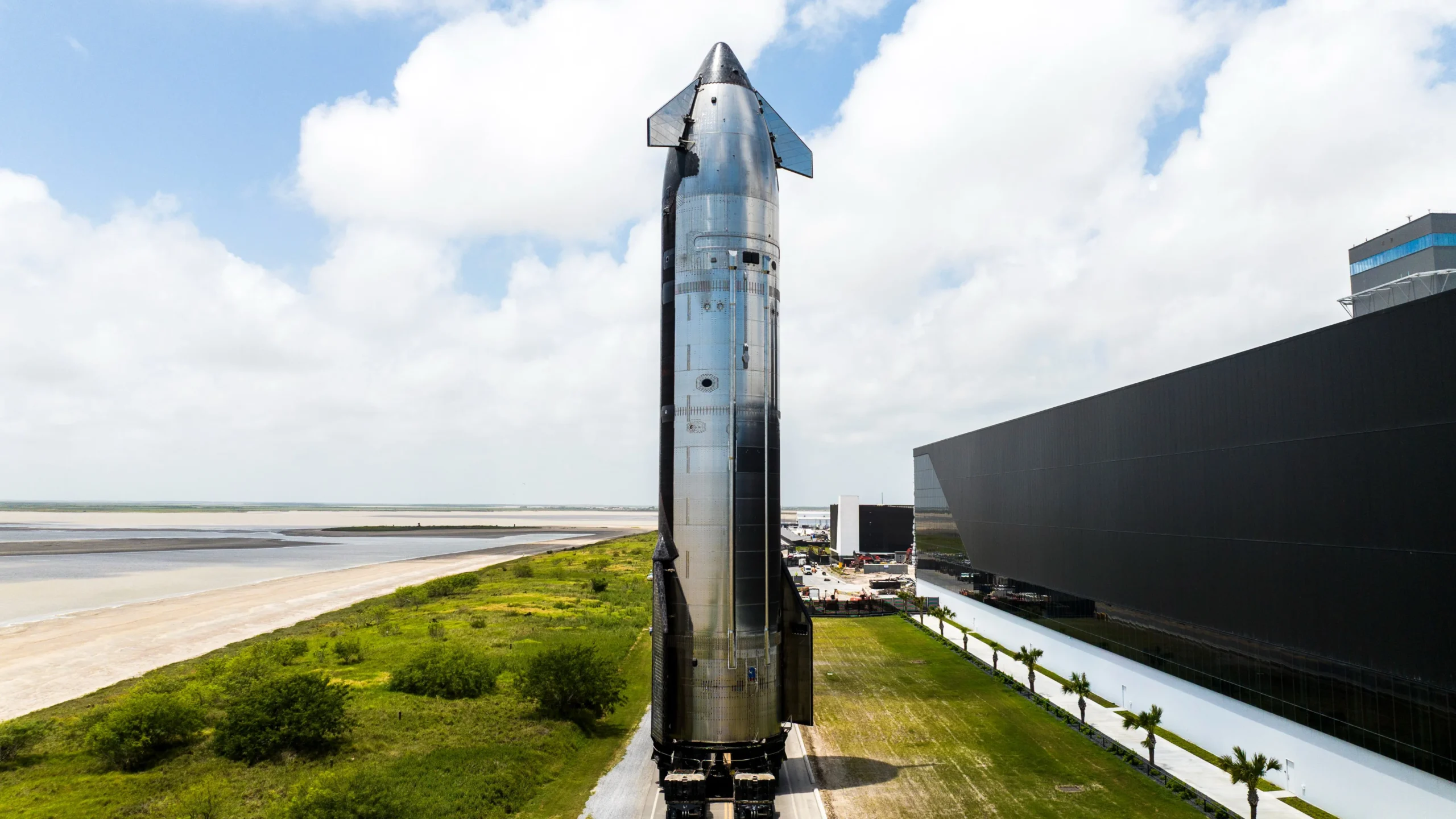

When SpaceX unveiled the radical shift from carbon fiber composite construction to 304L stainless steel for the Starship program, the aerospace industry was taken aback. For decades, high-performance launch vehicles had gravitated toward exotic composites and advanced aluminum-lithium alloys to achieve the lowest possible dry mass. Stainless steel, while exceptionally durable and heat-resistant, was traditionally dismissed as far too heavy for orbital-class vehicles. However, Elon Musk and the SpaceX engineering team recognized that for a fully reusable, high-cycle vehicle like Starship, the fundamental design equation changes dramatically. The superior performance of 304L stainless steel at cryogenic temperatures—where it actually gains strength without becoming brittle—and its extraordinary resistance to high-temperature oxidation fundamentally outweighed the material’s higher density.
The genius of the Starship V3’s hull design, however, lies not merely in the material selection but in a revolutionary variable-thickness structural philosophy. Traditional launch vehicle airframes are designed with near-uniform wall thickness, a simplification that reduces manufacturing complexity but imposes a substantial mass penalty. Starship V3 abandons this conservative approach entirely. Through advanced finite element analysis (FEA) and iterative physical testing, SpaceX has developed a hull structure where the thickness of the stainless steel skin varies continuously across the vehicle, precisely tuned to the local structural loads, thermal gradients, and manufacturing constraints encountered at every point on the fuselage.
Load Path Optimization: Mapping the Stress Topography
The structural design of the Starship V3 hull begins with a detailed understanding of the load paths experienced during its mission profile. During ascent, the vehicle experiences axial compressive loads from the immense thrust of the Super Heavy booster, aerodynamic pressure forces acting on the nose cone and forward sections, and lateral shear forces induced by atmospheric winds and vehicle maneuvers. During reentry, the load regime reverses and intensifies. The vehicle is subjected to high-velocity aerodynamic deceleration forces, characterized by a plunging nose-down attitude that produces significant bending moments along the fuselage. Simultaneously, the thermal protection system (TPS) must withstand plasma temperatures exceeding 1,600 K on the windward side, inducing non-uniform thermal expansion across the hull.
To address this complex, multi-axial loading environment, SpaceX engineers divided the Starship hull into distinct structural zones, each with its own optimized thickness profile. The lower barrel section, adjacent to the thrust structure, experiences the highest axial compressive loads during ascent. This region features the greatest nominal wall thickness, typically ranging from 4.0 to 5.0 millimeters. The mid-barrel sections, which encompass the primary propellant tanks, are subjected to the internal pressure of liquid oxygen and methane, as well as longitudinal bending loads. Here, the thickness varies from 3.0 to 4.0 millimeters, with additional stiffening from circumferential stringers and longitudinal weld seams. The upper sections, including the payload bay and forward dome, carry significantly reduced loads and feature thicknesses as low as 1.5 to 2.0 millimeters, achieving substantial mass savings without compromising structural integrity.
Cryogenic Thermal Contraction and Its Structural Implications
One of the most challenging aspects of the Starship V3’s hull design is accommodating the severe thermal contraction experienced when the propellant tanks are filled with cryogenic propellants. At the loading temperatures of liquid oxygen (90 K) and liquid methane (65 K), the 304L stainless steel hull contracts by approximately 0.3% to 0.4% in length. For a vehicle over 50 meters in length, this contraction equates to a dimensional change of 15 to 20 centimeters. If the hull were constructed with uniform thickness and unconstrained thermal expansion joints, this contraction would induce catastrophic weld failures and structural buckling.
SpaceX’s variable thickness approach ingeniously mitigates this challenge. By strategically varying the wall thickness and incorporating integrated stiffening rings at key longitudinal intervals, the engineers have created a structure that contracts uniformly and predictably. The thicker sections near the thrust structure and tank domes act as rigid anchor points, while the thinner barrel sections flex and contract with reduced stress. This controlled contraction prevents the accumulation of differential thermal strains that would otherwise lead to buckling or weld separation. Moreover, the thermal mass of the thicker lower sections acts as a heat sink, slowing the rate of cooling and reducing the magnitude of transient thermal gradients during rapid propellant loading.
Weld Optimization and Manufacturing Precision at Gigafactory Scale
| Hull Section | Primary Load Type | Nominal Thickness Range (mm) | Thermal Expansion Stress Level | Structural Reinforcement Element |
|---|---|---|---|---|
| Lower Barrel (Thrust Structure) | Axial Compression, Bending Moments | 4.0 – 5.0 | High (Thermal anchor point) | Heavy ring frames; reinforced weld joints. |
| Mid Barrel (Propellant Tanks) | Internal Pressure, Longitudinal Bending | 3.0 – 4.0 | Moderate to High | Circumferential stringers; integral baffles. |
| Upper Barrel (Payload Bay) | Aerodynamic Shear, Minimal Axial Load | 1.5 – 2.5 | Low to Moderate | Light ribbing; optimized for payload access. |
| Forward Dome & Nose Cone | Dynamic Pressure; Thermal Reentry Plasma | 1.2 – 2.0 | Low | Monocoque construction; integrated TPS mounts. |
| Aft Heat Shield Regions | Reentry Thermal Flux; Mechanical Shock | 3.5 – 4.5 | Extreme (Thermal cycling) | TUFROC tile attachment; metallic heat sink layers. |
The transition to variable thickness hull sections introduced significant manufacturing challenges. Traditional rolling and welding processes are optimized for uniform-thickness sheets. SpaceX addressed this by implementing advanced robotic welding systems at their Starbase and Cape Canaveral manufacturing facilities. These systems use precision seam trackers and adaptive heat input control to accommodate the varying thermal mass of different hull sections during welding. The variable thickness also necessitated redesigning the weld joint geometry, transitioning from simple butt-welds to stepped lap-joint configurations that enhance structural continuity and reduce stress concentrations at the thickness transition zones.
Mass Savings and Performance Impact: The Payoff
The variable-thickness design philosophy yields dramatic mass savings for the Starship V3. Estimates suggest that compared to a uniform-thickness design optimized for the maximum structural load condition, the variable-thickness approach reduces the dry mass of the hull structure by approximately 15% to 20%. For a vehicle designed to transport 100+ tonnes to low Earth orbit with full reusability, this mass reduction directly translates to a substantial increase in payload capacity or mission endurance. Moreover, the optimized mass distribution improves the vehicle’s center of gravity location and reduces the structural mass fraction, enabling more aggressive reentry trajectories and improved landing performance.
Beyond the direct mass benefits, the variable-thickness approach enhances the vehicle’s operational robustness. The thicker lower sections provide inherent resilience against the high-energy acoustic and vibration environments of launch, as well as the mechanical shock of recovery landings. The thinner upper sections, while lighter, remain sufficiently robust for payload integration and aerodynamic loads. This tailored structural performance ensures that every gram of steel is allocated where it contributes most effectively to the vehicle’s mission objectives.
Frequently Asked Questions About Starship V3 Hull Engineering
Frequently Asked Questions
How does the variable thickness affect the vehicle’s weld quality and fatigue life?
Variable thickness introduces weld geometry complexity, requiring adaptive welding parameters to maintain consistent penetration and avoid undercutting at thickness transitions. SpaceX addresses this through advanced control algorithms, real-time weld pool monitoring, and post-weld heat treatment. Fatigue life is maintained through careful fillet radii design at thickness transitions, ensuring stress concentration factors remain within acceptable limits.
Is the hull thickness measured pre or post cold-working (rolling)?
The thickness specifications are defined for the final, cold-worked state. SpaceX 304L stainless steel is typically supplied in a cold-rolled condition that increases yield strength to approximately 400-500 MPa. The variable thickness is achieved through careful rolling mill control and subsequent machining operations, ensuring final dimensions are accurate to within +/- 0.1 mm.
How does the variable thickness interact with the thermal protection system (TPS)?
The TPS attachment points are precisely integrated into the hull thickness profile. On the windward surfaces, where thicker steel sections provide greater thermal sink capacity, the TPS tiles are mounted with specialized isolation washers to manage differential thermal expansion. The thicker sections also allow for deeper mechanical fastening, ensuring the TPS remains securely attached during the high-vibration reentry phase.