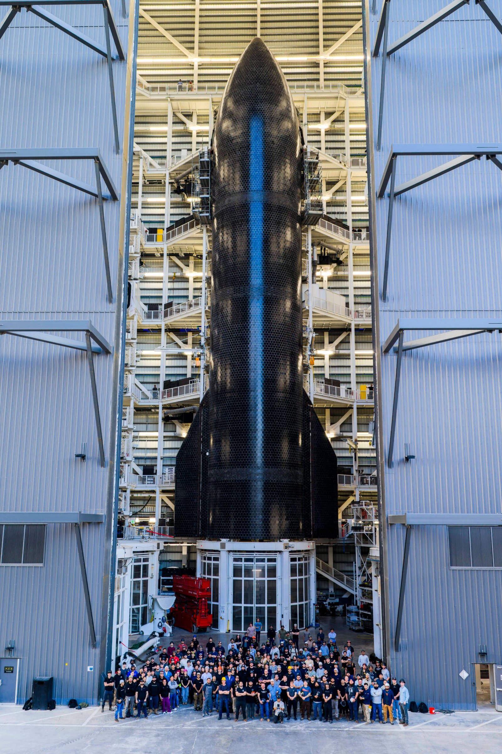

Propellant slosh represents one of the most insidious and potentially mission-critical stability challenges in large-scale liquid-propellant launch vehicles. In the context of Starship V3—a vehicle with cylindrical tanks exceeding 9 meters in diameter and holding over 1,200 tonnes of cryogenic propellant—the dynamics of sloshing fluids are magnified to an extraordinary scale. During the vehicle’s ascent, powered landing, and in-orbit propellant transfer operations, the liquid methane and liquid oxygen within the tanks experience intense accelerations, gravitational shifts, and rapid directional changes. If left unchecked, these fluid motions can generate catastrophic destabilizing forces.
The primary risk associated with uncontrolled slosh is the excitation of the vehicle’s structural resonant frequencies. When the natural oscillation frequency of the propellant mass aligns with the vehicle’s structural bending modes, the resulting coupling can produce a positive feedback loop where the sloshing fluid actually drives the vehicle into destructive oscillations. This phenomenon, known as pogo oscillation, was responsible for multiple mission failures during the early days of liquid-propellant rocketry, including notable incidents with the Saturn V’s second stage and the Atlas-Centaur vehicle. Additionally, slosh can expose the tank ullage (gas) ports, allowing high-pressure gas to be ingested into the engine turbopumps, a condition known as gas entrainment, which can cause immediate engine shutdown through cavitation or loss of prime.
CFD Modeling: The Virtual Testbed for Fluid Behavior
Traditional approaches to slosh mitigation relied on empirical scaling laws derived from subscale water tank tests and simplified analytical models. For a vehicle as large and dynamically complex as Starship V3, these methods proved hopelessly inadequate. SpaceX’s propulsion and structures teams turned to the most advanced computational fluid dynamics (CFD) tools available to simulate the full multiphase behavior of the cryogenic propellants under realistic operational conditions. These simulations employed volume-of-fluid (VOF) multiphase models, coupled with six-degree-of-freedom (6-DOF) motion solvers, to capture the complex interactions between the fluid free surface, the tank walls, and the vehicle’s instantaneous acceleration vector.
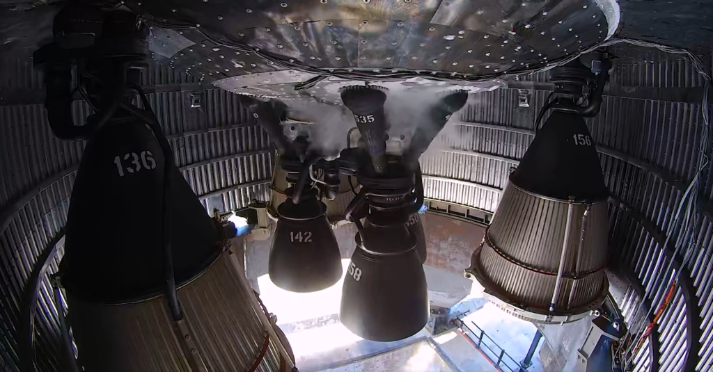
The CFD simulations were conducted across a vast parameter space, encompassing thousands of permutations of fill level, ullage pressure, acceleration magnitude, and slosh excitation frequency. The simulations utilized high-resolution, fully compressible flow solvers that accounted for the variable density of cryogenic fluids and the phase-change dynamics at the liquid-gas interface. Through these extensive numerical campaigns, SpaceX engineers identified that the conventional anti-slosh baffles—simple annular rings attached to the tank walls—were insufficient for the V3 configuration. The baffles effectively damped slosh at low fill levels but created resonance-enhancing vortices at medium and high fill levels, exacerbating the very problem they were intended to solve.
Baffle Geometry Optimization: From Annular Rings to Radial Fins
The breakthrough in slosh stabilization for Starship V3 came from a radical redesign of the internal baffle architecture, guided entirely by CFD-derived insights. The traditional annular ring geometry, which encircles the tank interior, was replaced with a sophisticated network of radial fin baffles, coupled with a central vertical damping plate. The radial fins extend from the tank walls toward the center, with carefully calculated spacing and perforation patterns optimized to disrupt both transverse and longitudinal slosh modes simultaneously.
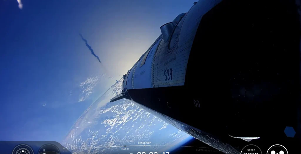
The CFD simulations revealed that the radial fin geometry effectively breaks the coherence of large-scale slosh waves by introducing multiple, overlapping free-surface disruption zones. Unlike annular rings, which allow slosh waves to propagate freely around the circumference of the tank, radial fins segment the fluid domain, creating localized damping regions. The vertical central plate, positioned coaxially with the tank’s longitudinal axis, provides additional damping for axial slosh modes, which are particularly problematic during the high-G ascent phase. The perforations within the fins—carefully sized to avoid clogging and maintain structural integrity—allow for controlled fluid communication between baffle compartments, preventing the formation of stagnant trapped volumes that could lead to gas entrainment during rapid attitude changes.
Ullage Pressure Management: A Dynamic Balance
| Slosh Mode | Excitation Cause | CFD Identified Damping Mechanism | Baffle Geometry Solution | Ullage Pressure Impact |
|---|---|---|---|---|
| Transverse (Lateral) Slosh | Aerodynamic side forces; wind shear | Radial fin segmentation; free-surface disruption | Perforated radial fins (4-6 fins per tank) | Minimal ullage pressure variation; maintains autogenous pressurization. |
| Longitudinal (Axial) Slosh | Ascent thrust fluctuations; stage separation events | Vertical central plate; fluid column breakage | Coaxial vertical damping plate (0.3-0.4 tank diameter) | Prevents ullage gas entrainment; maintains pressure stability. |
| Rotational (Swirling) Slosh | Vehicle pitch/yaw maneuvers; engine gimbaling | Spiral-angled fin edges; vortex breaking | Helical fin edge contours; integrated swirl breakers | Reduces ullage wall wetting; maintains thermal control. |
| Combined (Coupled) Modes | Complex acceleration vector combinations | Multi-axis damping; transient suppression | Multi-layer baffle arrays (stacked radial fins) | Requires active ullage pressure control algorithm. |
The CFD analysis also revealed an intricate relationship between slosh dynamics and ullage pressure management. In the Starship V3’s autogenous pressurization system, the ullage (the gas volume above the liquid propellant) is maintained by gaseous methane and oxygen tapped from the engines and rerouted through heat exchangers. The CFD models showed that during severe slosh events, the liquid propellant could temporarily ‘surge’ upward, flooding the ullage ports and causing a sudden drop in ullage pressure as the cold liquid thermally shocked the pressurization system.
To resolve this, SpaceX integrated the CFD results into a real-time ullage pressure control algorithm that modulates the pressurant flow based on tank acceleration and slosh state. The algorithm uses input from an array of high-bandwidth pressure sensors and accelerometers to predict incipient slosh events and proactively adjust ullage pressure, ensuring continuous gas flow to the engine inlets regardless of the fluid state. This active control strategy, refined through thousands of CFD simulation hours, has been a critical enabler of the V3’s rapid-refueling and in-orbit propellant transfer capabilities.
From CFD to Physical Validation: Subscale Testing and Full-Scale Data
While CFD provided the foundational design insights, the ultimate validation came from a rigorous physical testing program. SpaceX constructed a series of transparent subscale tank models, scaled at 1:4 and 1:8 of the full V3 geometry, and instrumented them with high-speed cameras, pressure transducers, and accelerometers. These models were subjected to simulated flight accelerations using a specialized shaker table capable of delivering multi-axis motions representing the full Starship flight profile.
The physical tests confirmed the CFD predictions with remarkable fidelity, validating the radial fin baffle geometry and the ullage pressure control algorithm. Importantly, the tests revealed subtle secondary effects that the initial CFD simulations had underpredicted, such as the formation of persistent gas bubbles trapped within the baffle cavities during low-acceleration coast phases. These findings fed directly into a second round of CFD optimizations, leading to the addition of vent slots in the baffle roots and refined perforation patterns. This iterative cycle of CFD prediction, physical validation, and design refinement exemplifies SpaceX’s aggressive engineering development methodology, enabling rapid convergence on a robust, flight-proven design.
Frequently Asked Questions About Starship V3 Slosh Dynamics
Frequently Asked Questions
Can slosh be entirely eliminated, or is it simply managed?
Complete elimination of slosh is physically impossible in any liquid-filled tank subject to acceleration. The fundamental physics of fluid inertia guarantee that some fluid motion will occur. The engineering objective is to manage the slosh dynamics to ensure that resonant frequencies are not excited, that gas entrainment is prevented, and that all slosh-induced forces remain within the vehicle’s controllability margins.
How does the variable thickness hull affect slosh dynamics?
The variable thickness hull has a secondary but important effect on slosh dynamics. The stiffened lower barrel sections, with their greater thickness and structural mass, alter the vehicle’s bending mode frequencies. The baffle design must be carefully coordinated with these structural modes to ensure that the slosh natural frequencies do not couple with any structural resonance. CFD models incorporate the full vehicle structural dynamics to optimize this coupled system.
What happens if the ullage pressure control algorithm fails during operation?
A failure of the ullage pressure control algorithm would likely lead to rapid propellant slosh growth and significant gas entrainment. The engine turbopumps would ingest ullage gas, causing immediate cavitation, loss of thrust, and potentially catastrophic engine failure. To mitigate this, the Starship V3 incorporates redundant pressure sensors, triple-redundant control computers, and manual override capability for the flight crew, ensuring that a single-point failure cannot compromise the vehicle.